Research Progress in Corrosion Protection Technology for Electronic Components
Abstract
As a necessary part of all electronic devices, equipment and systems, electronic
components play a vital role in the global economy. Since the corrosion of a single
electronic component may directly affect the normal operation of the entire
electronic system, the failure of electronic components has now become the most
important cause of electrical system failure of concern to key electronic
technologies. Therefore, it is urgent to study the corrosion failure process of
electronic components and the means of effective protection. In this paper, starting
from the corrosion types and influencing factors of electronic components,
especially chips, we introduce the influence of humidity, temperature, salt spray,
and environmental particles, as well as the device’s own surface roughness,
material adhesion, semiconductor materials, metal coupling system, and lead-free
solder system on corrosion performance in the environment. Subsequently, this
paper summarizes how to protect electronic components during processing, and
sums up the types of electronic component protections, and the specific corrosion
protection process for the three commonly used types of chips, namely, the indium
antimonide InSb chip, the IC chip, and the Sn–Zn solder chip, for reference. Finally,
future development trends in the corrosion protection of electronic components are
anticipated and summarized.
1. Introduction
The 14th Five-Year Plan” emphasizes the need to “accelerate digital development
and build a digital China” [1]. In the process of transformation and upgrading of the
global manufacturing industry towards intelligence, the basic equipment control
system, especially the electronic components, bears an unshirkable responsibility,
and has become the key to structuring the digital economy. Electronic components
include common electromechanical components, semiconductor discrete devices,
optoelectronic devices, electric vacuum devices, microwave devices and
components, and integrated circuits. Among them, the chip is the basic carrier of
the integrated circuit and is also the collective name for semiconductor electronic
components.
The ongoing development of electronic components towards miniaturization and a
high degree of integration is now placing higher demands on the reliability of single
components. The degree of corrosion of electronic components determines their
electrical functional characteristics, including the safety as well as the reliability of
the system. Currently, the failure of electronic components accounts for 70% of the
causes of failure in electrical systems [2]. The corrosion of electronic components
is mainly due to atmospheric corrosion; the corrosion types include uniform
corrosion, pitting corrosion, galvanic coupling corrosion, intergranular corrosion,
corrosion under stress, crevice corrosion and microbial corrosion. In hot and humid
climates, such as the South China Sea islands and other special environments,
high temperature, high humidity, and high salt spray together constitute harsh
conditions that can cause serious corrosion effects on electronic components. The
same batch of navigational equipment operating in the islands and reefs of the
Cangzhou environment showed three times greater levels of corrosion than when
used in less harsh environments [3]. The intensification of corrosion means that
the probability of failure of electronic components increases. Zhang et al. [4] found
after three years of field research that the failure rate of electronic equipment in
aircraft serving in coastal airport environments was two to three times that of
aircraft serving inland. As a key component of electronic components, chips play
an important role in the national economy and play an important role in the
country’s economic development. So, in order to improve chip life and reduce
product costs, chip corrosion protection technology is in urgent need of
development. In view of this, the study of the mechanisms of corrosion damage of
electronic components, and the taking of protective measures to improve the
service life of electronic components for the development of the electronic
components industry has important economic as well as social benefits.
However, at this stage, the corrosion failure and protection technology of electronic
component materials has not received much research progress. In view of this,
this paper summarises the existing research results in electronic component
corrosion and protection, integrated circuit corrosion and other related fields [5,6].
This paper summarises the impact of different environmental factors on the
corrosion of electronic components, focusing on an overview of the manufacturing
process of electronic component processing and protection technology, as well as
corrosion protection methods for several common chip types. This paper analyses
the material properties, which provide a reference for chip corrosion protection.
Finally, it looks forward to the future development trend of corrosion protection of
electronic components.
Analysis of the Causes of Corrosion
The diversity of materials used in electronic components and the complexity of the
application environment make the types of corrosion of electronic components
diverse. The main type of corrosion that leads to the failure of electronic
components is atmospheric corrosion. Atmospheric humidity, temperature, salt
spray, environmental particles, and the surface roughness, adhesion, and welding
materials of the material system of the electronic components are the main factors
influencing their corrosion.
Types of Electronic Component Corrosion
The main type of corrosion leading to the failure of electronic components is
atmospheric corrosion. Depending on the environmental humidity and liquid film
thickness, atmospheric corrosion can be divided into dry corrosion, moisture
corrosion, and wet corrosion. The relative humidity (RH) is an important factor
affecting the rate of atmospheric corrosion, representing the water vapor pressure
in the air and the percentage of saturated water vapor pressure under the same
temperature conditions. When the humidity increases to a certain value, the
amount of moisture absorption increases sharply; this certain value is called the
critical relative humidity (CRH) [7].
Figure 1 in the I area image shows that, at this time, the surface thickness is δ =
10~100 Å. Because the relative humidity is very low, the material surface cannot
easily form a liquid film. Many metal surfaces will form an oxide film, the corrosion
rate is extremely low, and a dry corrosion process occurs. In the presence of trace
gaseous pollutants, copper, silver, and other non-ferrous metals, form thin films,
which are known as loss of color. Silver, for example, loses its luster in air. When
the relative humidity is greater than the critical relative humidity, the metal surface
liquid film thickness to meet the δ = 100 Å~1 μm; that is, in Figure 1 in the II zone
location, the material is in the tide corrosion state. Aqueous films containing gases
such as CO2, H2S and SO2 cause severe corrosion of non-metallic materials and
alloys such as steel, copper, nickel and silver. For example, silver loses its lustre
on contact with hydrogen sulphide, forming a film that loses its lustre with sulphide,
while copper stains and turns black. When humidity reaches 100%, a wet corrosion
phenomenon is obvious; the surface liquid film thickness can be clearly observed
by the naked eye, as shown in Figure 1 in the III area [7]. Under alternating wet
and dry conditions, the dry corrosion product film may absorb moisture from the
air and bring moisture into contact with the metal surface, thereby increasing the
rate of corrosion of the metal. Green skin formation on copper, such as caliche,
and structural steel corrosion, are common examples of corrosion caused by
humid atmospheres.
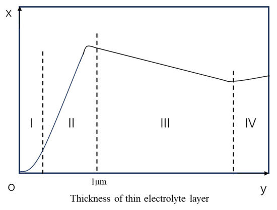
Figure 1. Corrosion rate at different liquid film thicknesses (The liquid film on the
surface is divided into regions I–IV depending on the thickness of the liquid film)
Study of the Influence of Environmental Factors on the Corrosion of Electronic Components
Due to the long-term exposure of electronic components to the environment,
temperature, humidity, salt spray, and environmental particles influence the
corrosion performance of their surfaces. Wang [8], in considering the environmental factors of chip corrosion failure, states that the corrosion mechanism is mainly affected by high humidity environment and high temperature gas environment. Related research points out that the protection of chips should start from the perspective of the degree of air contact, the ambient temperature, and the humidity in order to take relevant steps [9]. It can be seen that the impact of environmental factors on the corrosion of electronic components cannot be
ignored.
Humidity
Environmental humidity is the basis for the classification of electronic component
atmospheric corrosion. When the relative humidity of the atmosphere is greater
than the critical relative humidity, water vapor from the air condenses and
precipitates to form “dew droplets”, a condensation phenomenon, resulting in the
formation of a liquid film on the metal surface [10].
Once the ambient humidity exceeds the critical relative humidity, the electronic
components’ surface liquid film, atmospheric O2, and other corrosion media will
dissolve into the surface liquid film to form an electrolyte film. Then an oxygen concentration cell is formed and electrochemical corrosion occurs [11]. Since the atmospheric corrosion rate mainly depends on the electrochemical reaction in the
electrolyte film on the metal surface, the higher the relative humidity and the higher the thickness of the surface liquid film, the easier it is for condensation to occur on
its surface with increased risk of corrosion. Electronic components absorb and
release moisture from the atmosphere as the local relative humidity rises and falls. Problems caused by moisture absorption include delamination and pockmarking of circuit boards, as well as blowholes, solder blowholes, and solder blowout in plated-through rectifiers. Ren et al [12] stated that when the water film forms a
metal corrosion cell with separated cathode and anode, the metal on the chip
surface loses electrons through oxidation, while the water film ions undergo electronic reduction and the post-corrosion polarisation slows down. Fu et al. [13],
in a related chip corrosion study, also confirmed that the action of water vapor on
the metal produced the phenomenon of electrochemical corrosion diffusion, which
can be explained by the above corrosion mechanism. This suggests a way of preventing corrosion caused by environmental humidity, i.e., blocking electrochemical corrosion by preventing the formation of water films on the surface of electronic components.
Temperature
Electronic components can be classified as commercial grade (0 °C to 70 °C),
industrial grade (−40 °C to 85 °C), or automotive grade (−40 °C to 125 °C)
depending on their operating temperature [14]. When the humidity in the
environment where the electronic components are located does not reach the
critical relative humidity, wet corrosion does not occur; however, at this time, the
electronic components also have the problem of dry corrosion. Li [15], in an IC
plastic sealing study, proposed that dry corrosion is mainly a high-temperature
oxidation phenomenon. When a metal part in a chip generates an oxide film under
the action of high-temperature gases, the corrosion resistance of the metal is
closely related to the characteristics of the oxide film, including the coverage and
thickness of the oxide film, as well as the forming speed and morphology. In
addition, temperature stresses due to temperature changes can also have an
impact on the spread of corrosion defects. With regard to temperature failure, Lu
et al [16] pointed out that defects diffuse to varying degrees under the effect of
stresses generated by temperature changes. The parameters of the components
change up and down at high or low temperatures, and return to normal only at
room temperature and in the open-circuit state. The influence of temperature on
the corrosion of electronic components is, on the one hand, closely related to the
condition of the ambient humidity, and, on the other hand, the loss of electronic
components is mainly dominated by stress corrosion
Salt Spray
Salt spray environments including salt, chloride, nitrate, phosphate, and other
particles, will cause electrochemical corrosion of metal leads and solder in the
device, thus causing the failure of electronic components. As salt spray particles
are mostly about 5 μm in diameter, the small particle size results in high
permeability, so its corrosion of electronic components is obvious. Salt spray has
the following effects:
1. Chloride attached to the surface of electronic components can easily absorb water,
promoting the formation of surface liquid film, further accelerating the occurrence
of wet corrosion and tide corrosion, and ultimately leading to the failure of
electronic components.
2. Chloride ions in a salt spray can penetrate and destroy the surface coating of
electronic components and passivation film, and form soluble compounds,
eventually inducing hole corrosion.
3. Salt spray particles accompany the atmospheric flow and settle on the surface of electronic components, which can cause blockage or jamming of electronic components’ movable devices, leading to equipment failure.
Environmental Particles
Air contains SO2, O2, and H2, which, in contact with electronic component leads,
results in certain corrosion phenomenon. Al wire used for chip connection is more
active and contact with air produces a corrosion-resistant oxide film, which can
slow down the electrochemical corrosion effect while oxidizing the corrosion [17].
In a study on the corrosion of Al and SO2, Han et al. [18] pointed out that the
corrosion efficiency of Al increases with time, whether in dry or wet conditions. In
the production of plastic sealing process of electronic components exposed to Clionomer impurities will be with the continuous extension of the exposure time, so
that the surface of the electronic components of the alumina film in the corrosion
products gradually transformed into aluminium chloride, from chemical corrosion
to electrochemical corrosion, increasing corrosion hazards [17,19].
In addition, residual hydrogen atoms also have a negative impact on the
performance of electronic components. As the temperature rises during the
heating process of the soldering process, the hydrogen present in the air and the
hydrogen carried by the chip material itself continuously penetrate into the chip
semiconductor material under the influence of molecular thermal motion and
enhance the dislocation movement in the semiconductor crystal structure. The
lattice distortion caused by dislocations can severely scatter carriers and affect
mobility, which, in turn, leads to degradation of the semiconductor properties
[20,21].
Study of the Influence of Electronic Components’ Own Factors on Corrosion
In addition to the environmental factors that lead to the corrosion of electronic
components, the structure of the device itself and the choice of materials will have
a certain impact on the corrosion effects. The structure of the electronic component
itself is mainly affected by the flatness of the surface, scratches, roughness,
surface welding gaps, etc.; material influences mainly include material adhesion,
barrier and semiconductor materials, and metal coupling corrosion, etc.
Surface Roughness
The influence of surface roughness on the corrosion of electronic components is
particularly prominent in chip types. Liu et al. [22] pointed out in a chip surface
roughness study that, when the chip surface roughness does not meet ideal
conditions when the adsorption force is enhanced, the phenomenon of adsorption
of metal ions is prone to occur, resulting in increased leakage current and
performance degradation. Moreover, in the chip manufacturing process, different
welding methods will make the chip surface weld, resulting in increase in
roughness increases, increasing the corrosion rate. Robert [23] carried out
electronic materials and devices corrosion research, highlighting the chip
chromium/solder interface failure process, as shown in Figure 2a. The results
obtained showed that, in the porous chromium layer, after welding, surface
roughness increased. In the chromium/solder interface, defects allowed water in,
resulting in oxide growth, and corrosion was accelerated. Figure 2b shows a
cross-sectional schematic of a printed chip circuit board, showing copper
hydroxide filaments growing along the interface between resin and glass fiber, with
crevice corrosion. This argues that the solder gap increases the surface roughness
of the chip and has an indirect effect on chip corrosion.
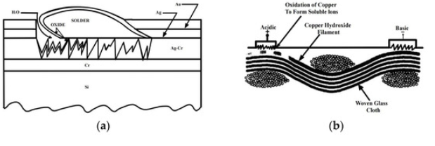
Figure 2. (a) Schematic diagram of the failure process at the chip
chromium/solder interface [23]. (b) Schematic diagram of the cross-section of the
printed chip circuit board [23].
Guo et al [24] carried out an experimental analysis on the basis of this for the
problems of rough surfaces after corrosion, corrosion pits, and “bright spots” after
fine polishing, and obtained that the grinding and polishing process can reduce the
surface roughness of the chip, but it is easy to form irregular defects and dark
damage, these conditions will accelerate the chip corrosion, so it is necessary to
determine through experimental methods what speed and pressure For the
surface conditions that cannot be improved by grinding and polishing, it is
necessary to eliminate the dark damage that occurs on the metal surface during
the grinding and polishing process by means of a corrosive solution. The results
of the study show that as the speed of grinding and polishing increases, the
irregular defects and dark damage on the metal surface increase, and the speed
is too fast to make the material and the polishing solution work unevenly and
produce more defects. Similarly, The results of the study show that as the grinding
and polishing pressure increases, the force between the material and the
workpiece increases, and the surface force is not uniform, which speeds up the
fine grinding rate and increases the material damage, so the pressure should be
reduced.
Material Adhesion
Anderson et al. [25] evaluated and optimized the effect of various adhesion
treatments by conducting adhesion tests on different substrates, especially poorly
adhered substrates, and concluded that poly(parylene) as a coating material
showed strong adhesion during chip encapsulation and a stable process during
corrosion protection. In corrosion tests on material coatings, it was also concluded
that poly(parylene) coatings play a crucial role in protecting copper wires from
corrosion. The role of material adhesion in chip corrosion was also confirmed by
Kotzar et al. [26] in their tests on material adhesion.
Coupled Systems of Semiconductor Materials and Metals
Semiconductor materials, as core materials for the manufacture of electronic
components, play an important role in the design, manufacture, and packaging of
electronic components [27,28]. Metals and their alloy materials, as the main
materials used to make the internal fittings of electronic components, assume a
key role in the miniaturization of chips through the continuous implementation of
technologies such as small capacitance and high adhesion. However, when a
semiconductor and a metal come into contact, an interface with discontinuous
energy levels is formed, leading to a change in the electron energy distribution,
which, in turn, causes a change in the electronic structure, with electronic structure
adjustment and charge redistribution phenomena occurring and a semiconductor–
metal interface effect [29,30]. This change in electronic structure affects the charge
density and electric field distribution at the semiconductor–metal interface, which
in turn affects the performance of the device.
In a coupled system of semiconductor materials and metals in chips, Li et al. [31]
confirmed that semiconductor materials can influence or change the direction of
electron transfer between the metal and the semiconductor surface, thus making
the metal material easy to be corroded or slowing down the corrosion rate. This
provides an idea and research basis for the study of corrosion in complex systems
and environments by promoting the mechanism of corrosion in coupled systems
of semiconductor materials and metal materials in chips. For systems that are not
easy to passivate, Zhang [32] pointed out that the work function of N-type
semiconductor materials should be lower than that of metals, and should have
lower conductivity and cathodic reaction catalytic activity; for systems that are easy
to passivate, the “corrosion-promoting activity” of semiconductor materials can be
used to strengthen the self-healing of passivation films and achieve high efficiency
of the metal The “corrosion-promoting activity” of semiconductor materials can be
used to enhance the self-healing of the passivation film and to achieve high
corrosion resistance. The study of “corrosion promoting activity” confirms the effect
of the direction of electron transfer between the metal and semiconductor surfaces
on the rate of corrosion of metals.
Lead-Free Solder Systems
Lead-free solder systems mainly consist of metal powders, a small amount of flux,
and trace additives [33]. Considering the actual application scenario of electronic components, the lead-free solder used needs to have good electrical and thermal conductivity and should also have an ideal melting point [34], so the metal solder
powder is mostly composed of a variety of metal elements [35]. As Sn melts at around 232 °C and has good wetting properties, the tin ratio in the general
composition of lead-free solder is often higher than 90% [14]. Compared to the traditional lead-containing solder used, which releases toxic metal lead and may endanger human health and the environment, the lead-free solder system is more
environmentally friendly and more in line with health requirements; lead-free solder
is now widely used in chip packaging in the electronics industry [36]. Common
types of lead-free solder include Sn–Ag–Cu, Sn–Ag, Sn–Cu, and so on [37,38]. It
is worth noting that, as most of the lead-free solders used at this stage contain
elements such as boron, silver, and copper, most lead-free solders have performance deficiencies compared to lead-containing solders, such as insufficient oxidation resistance [39], which makes chips encapsulated with lead-free solder systems more prone to corrosion and, thus, affects chip life.
Jaffery [39] et al. investigated the corrosion resistance of lead-free solders in
different corrosive media and found that the ratio of Cu and Ag in the solder played
a significant role in the corrosion behavior of Sn–Ag–Cu solders as well as Sn–Cu
solders. Using FESEM photographs (shown in Figure 3) [40], the results showed
that the addition of Fe and Bi exacerbated the lamellarisation of the material
surface, increasing the surface area of the material and, thus, the solder corrosion.
From Figure 4a [41], it can be seen that the addition of 0.05% Ti significantly
increased the arc resistance of the solder, and, from Figure 4b [41], it can be seen
that the impedance modulus value also increased significantly, which indicates that
the corrosion resistance of the solder was significantly enhanced after the
modification by Ti. The addition of 0.05% Ti to Sn–9Zn solder can form a more
uniform and fine eutectic structure, reduce the number of Zn-rich phases, and,
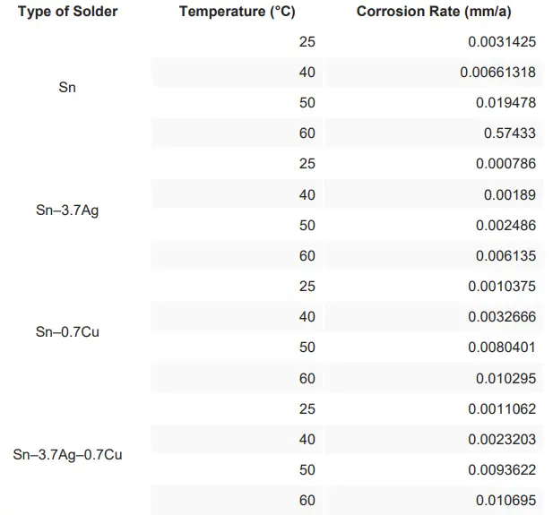
thus, improve the corrosion resistance of the solder. It has been shown that, at all
temperatures, the corrosion rate of Sn is always the highest, the corrosion rate of
Sn–3.7Ag is always the lowest, and the corrosion rates of Sn–3.7Ag–0.7Cu and
Sn–0.7Cu are in the middle of the range (as shown in Table 1) [42]. Jaffery et al.
showed that the types and proportions of elements added to different types of leadfree solders have a great influence on the corrosion resistance of the solder, which
also provides a new research method for the future development of lead-free
solders with high corrosion resistance.
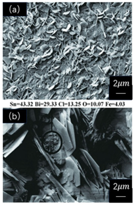
Figure 3. FESEM micrographs of solder alloys after complete polarization. (a)
Sn–Cu; (b) Sn–Cu–Fe–1Bi [40].
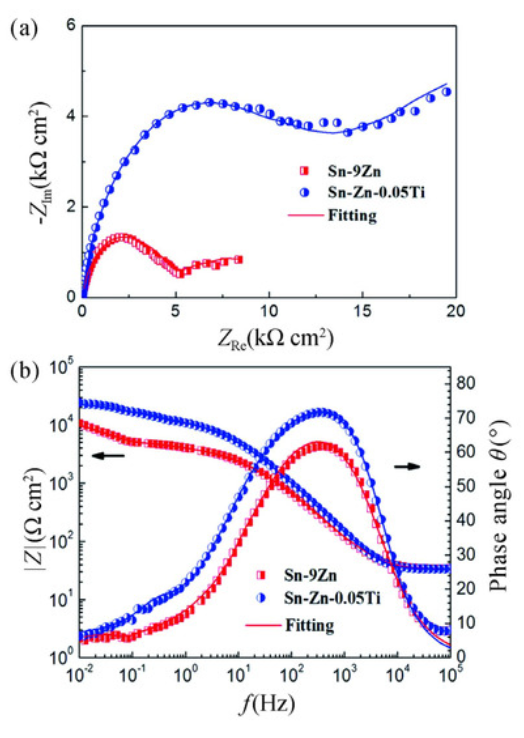
Figure 4. Spectra of Sn-9Zn and Sn-9Zn-0.05Ti solders. (a) Nyquist plots; (b)
Nyquist plots [41].


Table 1. Corrosion rate obtained from 3.5% NaCl solution for Sn–3.7Ag–0.7Cu,
Sn–0.7Cu, Sn–3.7Ag, Sn at different temperatures [42].
Protection Processes
Protection Processes for Manufacturing and Packaging Processes
The protection process used in the manufacturing and packaging of electronic components determines the final corrosion resistance of the overall device. Considering the chip manufacturing process as an example, chip manufacturing is mainly divided into chip design, wafer production, packaging production, cost
testing, and other major links, while crystal manufacturing and packaging manufacturing is the key to the final performance of the chip. In the manufacturing
and packaging process whether the process performance is good or bad will ultimately lead to the chip corrosion effect of fast or slow; the above two processes impose certain anti-corrosion measures, which can effectively slow down the
degree of chip corrosion later.
Manufacturing Protection
The processes of chip manufacturing are exposed to the environment, and
pollutant particles in the environment can adhere to the chip surface and cause
chip corrosion at a later stage, so environmental pollution control techniques need
to be strictly enforced. The control technology includes indoor and outdoor air
pollution control technology, pollution control technology, etc. Meanwhile, with the
continuous rapid development of ultra-large-scale integrated circuit production
technology, the scientific and technological community has imposed more
stringent requirements for the production environment chemical pollution control
index. Therefore, the following measures are focused on protection in the chip
manufacturing process:
1. When designing the passivation layer for the bonding of the chip to the packaging
material, attention should be paid to improving the resistance to water vapor
corrosion in the pressure zone of the IC while not affecting the bonding quality.
2. Controlling the etching process of the aluminum layer in the bonding area,
extending the chemical cleaning time after etching, and reducing the residue of
fluorinated compounds on the surface of the aluminum layer [43].
3. The storage and transportation environment of the chips in the post-etching period
must not be too humid, and packaging materials must not use materials containing
fluorine and halogen elements.
In industrial practice, the chip manufacturing protection process for the final corrosion resistance of the finished product plays a crucial role; however, current actual production and manufacturing factory corrosion awareness is not strong the protection process needs to be upgraded.
Encapsulation Protection
As a common integrated chip protection technology, plastic-sealed chips have
contributed to the size, lifetime, and functionality of chips. In a study by Zhou et al.
[44] on plastic-sealed integrated circuits, it was pointed out that the non-enclosed
nature of the plastic seal makes the chip subject to water vapor intrusion corrosion
as well as airborne contaminant corrosion. Hermetic packages rely on a solid
enclosure made of impermeable material, and are sealed to protect electronic
components by keeping them in an environment with low relative humidity. Internal
water content can come from stagnant water within the package before and during
sealing, as well as from outgassing of adsorbed molecules. Therefore, the
following controls can be implemented on the chip package:
1. Choosing a suitable environment for placing the chip after opening the package
and controlling the time it is exposed to purified air.
2. Prevention of delamination and moisture absorption problems in the plastic seal is
the key to packaging chips.
Yu et al [45] found that at the same potential, the NDr value of solder in alkaline
solution is lower than that in acidic solution (as shown in Figure 5), which means
that the passivation film in alkaline environment has better corrosion resistance.
The environmental conditions of chip storage will affect the corrosion resistance of
the solder on the chip, which in turn affects the overall performance of the chip.
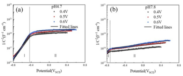
Figure 5. MS curves of solder Sn-0.7Cu in different environments (acidic (a) and
alkaline (b) artificial sweat) [45].
At the same time, the packaging material serves as a barrier to isolate the chip from the surrounding environment. By choosing green, highly adhesive, lowstress, and low-moisture absorption packaging materials, the contact between the chip surface and water, dust, and other substances in the environment, can be
effectively reduced, thus reducing the strength of corrosion, and extending the life
of the chip [46].
For common sealing materials, the encapsulation material must have high purity
to reduce the concentration of Na+ and Cl− plasma impurities in the plastic sealing
materials to avoid the impurity ions leading to accelerated corrosion; for the filler
material, higher adhesion is required to prevent corrosion of the aluminum layer in
the molded area due to moisture intrusion [47]. Moreover, the addition of ion
trapping agents during the production of plastic sealing materials has the same
effect on the control of encapsulation materials [48].
The bio-implantability of new chips has now developed into a research “hotspot” in
medicine, electronics, materials, and their interdisciplinary aspects. As implantable
chips typically remain in the body for decades, their corrosion resistance needs to
be further developed and tested for high-accuracy predictions to mitigate chip
corrosion or adverse tissue effects. The key to improving the corrosion resistance
of implantable chips is to ensure their implantation integrity (Anne et al. [49]), which
must ensure that the chip functions properly for its expected lifetime and does not
damage the organism after implantation. Common materials used to encapsulate
biomaterials are metals, glass, ceramics, and polymers, with polymeric
encapsulants, particularly poly(parylene), often used for their corrosion resistance
and stability [50]. However, the containment properties of polymers are limited relative to other plastisol materials [51]. On this basis, Hogg et al. [52] proposed
polymer multilayer stacks for implantable chip packaging materials, where the lack
of molecular density of the polymer and the low permeability of the SiOX layer form a stack as a means to achieve the required closure for chip protection. Therefore,
for implantable chip packaging materials, the choice of polymer multilayer stacking
applications is preferable.
Types of Protection Processes
Electronic component protection processes can be divided into physical and chemical-electrochemical protection, depending on the principle of protection. Physical protection is achieved by adapting the process to the characteristics of the environment in which it is used, while chemical-electrochemical protection
extends the chemical or mechanical properties of the material by applying
protective coatings to increase the degree of protection
Physical Protection
Physical protection mainly considers the environmental effects outside the
electronic components and protects them from harmful effects, such as moisture
and electromagnetic radiation. In terms of physical protection, the following
protective measures can be carried out:
1. Improve the encapsulation hermeticity: choose high-quality encapsulation
substrates, sealants, and filling media as encapsulation materials, and, at the
same time, strictly follow the encapsulation process requirements to execute each
encapsulation step, such as curing and hot-pressing welding, to ensure the stability and consistency of the process parameters. A strict inspection system should be established during the encapsulation process to screen and deal with possible
defects in a timely manner to ensure that each encapsulated part is defect-free
and hermetically sealed.
2. Post-treatment of the welding and assembly process: The post-treatment of the
welding and assembly process refers to the relevant treatment carried out at the
end of the welding or assembly process. For example, the use of cleaning
solutions, ultrasonic cleaners, and other cleaning methods to remove the surface
of electronic components, such as oxides, oil, solder slag, and other impurities
[53]; the need to encapsulate the components through drying, vacuum drying and
other ways to ensure the dryness of their internal features, so as to extend the life
of electronic components. The purpose of post-treatment of the soldering and
assembly process is to eliminate impurities, such as condensation and chemical
substances, that may have a negative impact, thus achieving a protective effect.
Chemical Electrochemical Protection
Chemical electrochemical protection mainly uses the coating of protective coatings
to increase the corrosion resistance [31]. Electrochemical corrosion protection is a
method of preventing or mitigating metal corrosion by applying measures to metal
equipment based on electrochemical principles to make it the cathode in a
corrosion cell. In the application of electronic components, chemical
electrochemical protection technology needs to take into account the physical and
chemical properties of the protective coatings, the device, the environment, and
other factors to ensure that the protective effect is reliable. Special attention needs to be paid to the thickness of the protective coating on the surface and
consideration should be given to the tolerance fit between the components to
prevent the coating from being too thick, leading to component sealing failure and
resulting in accelerated corrosion.
In addition, in hot and humid climates, the South China Sea islands and other
special environments, taking into account the high temperature, high humidity and
high salt spray environmental conditions, condensation evacuation technology,
terminal sealing technology, space rust inhibitors, flow sealing technology, etc.,
can be used to prevent chip surface condensation and, thus, achieve the purpose
of protection.
Protection Processes for Several Common Chip Materials
The corrosion protection process for electronic components needs to be
determined with respect to the specific type, material selection, and application
scenario of the electronic components. Considering the application range and
frequency of various types of electronic components under actual circumstances,
the commonly used indium antimonide chips, microelectronic devices (IC chips), and Sn–Zn solder chips are analyzed for the protection process, respectively.
Indium antimonide (InSb) chips are widely used in military applications, such as
infrared detectors, astronomical observation, and missile positioning, due to their unique physicochemical properties and excellent compatibility, as well as their
outstanding performance in infrared detection [54]. IC chips are widely used in
everyday home appliances, televisions, computers, stereos, and cameras as a
type of chip that integrates a large number of miniature electronic devices in an
integrated circuit. In the manufacturing process of semiconductor chips, soldering
technology plays a crucial role. Sn–Zn solder is a lead-free solder, which is widely
used in the manufacture of Sn–Zn solder chips in electronic products because of
its low melting point and good fluidity [37].
InSb Chips
Considering PCB failure analysis techniques, Zhou et al. [55] conducted a study
of the surface after corrosion. When a chip undergoes corrosion, its surface
becomes uneven. Similarly, when an InSb chip undergoes corrosion, the
roughness of its surface makes the current on the chip cause an increase in
leakage current and a decrease in chip performance. Using the opposite idea, the
surface roughness of the chip can be repaired as a way of implementing a rehealing technique for corroded chips [17]. However, due to the low hardness of the
material of this chip, it is not easy to master the strength required when performing
polishing [56]. Bouslama et al [57] experimentally verified that the repair of
corroded chips can be solved under the following conditions: when the pressure is
lower than 4.5 N, the speed is lower than 80 r/min, the feed ratio is 1:1, the drop
rate is less than 1 drop/s, or the addition of oxidising agent H2O2 repairs the
corroded bumps on the InSb chips.
IC Chips
With regard to the corrosion of IC chips, Fu et al. [13] pointed out that it is often
related to the ambient humidity and temperature as well as the chlorine and copper
plasma in the air. Therefore, the protection of IC chips should start from these
points:
1. Adjusting the reflow soldering oven temperature profile to appropriately increase
the initial pre-treatment time and temperature and reduce the amplitude of
temperature change on the components;
2. Strengthening the sealing effect on the chip to prevent electrochemical corrosion
of airborne ions with the chip [58].
Although there are differences in the causes of corrosion between InSb chips and
IC chips, the reasonableness of the above chip protection techniques can be seen
in the protection measures for both.
Sn–Zn Solder Chips
Sn–Zn-based, Pb-free solders have poorer corrosion resistance than other Snbased, Pb-free solders due to the extremely high chemical activity of Zn in Sn–Zn
solders and the susceptibility of Sn–Pb alloys to oxidation and corrosion [37]. For
Sn–Zn solders as a class of Pb-free solders, alloying is the most common means
of improving the corrosion resistance of Sn–Zn solder chips. The results of Zhao
et al. [59] showed that the addition of trace amounts of Ag to Sn–Zn solders can
generate Ag–Zn IMC, which inhibits Zn chemical activity and, thus, improves its
corrosion resistance. In addition, once corrosion products are generated on the
surface of Sn–Zn solder chips, the pores, pits, and cracks on the surface will lead
to further contact with the corrosive medium, thus accelerating corrosion. The
addition of trace amounts of Ti can slow down electron transfer and stabilize the
surface area of the solder by means of a uniform, dense passivation film formed
on the surface of the alloy, thereby enhancing its corrosion resistance [41]. It is
worth noting that, when too much Ti is added, exceeding 0.1% of the alloy mass
fraction in the Sn–Zn solder, the continuous arrangement of corrosion products will
be broken due to the generation of Sn3Ti2 and Sn5Ti instead, expanding the
contact surface area and leading to accelerated corrosion [60].
Future Perspective
With the development of the global semiconductor industry, chip manufacturing
technology ushered in a golden period of rapid development, and moved the
electronic components industry into a new period. The rapid development of
electronic component manufacturing is closely related to the success of high-end
and small component manufacturing [61,62,63]. Based on the market
development in recent years, the following development directions for improving
the corrosion resistance of electronic components are proposed:
1. Research into the development of semiconductor packaging materials towards
higher adhesion, containment, and corrosion resistance;
2. In the process of shrinking the size of electronic component manufacturing, key
properties, such as low resistance and high adhesion of metals in chips and other
critical materials, need to be improved;
3. Considering the polluting and highly toxic nature of lead, conventional Sn–Pb
solders are in urgent need of environmentally friendly lead-free alternatives.
4. Indoor accelerated simulation tests continue to improve through the simulation of
realistic conditions of electronic component application scenarios, such as salt
spray tests, to explore the mechanism of different impact factors on the role of
electronic components.
The stability and reliability of electronic components not only depend on the choice
of key technical materials in the research and development process, but the manufacturing and packaging process is also crucial.
5. Summary
This paper analyses the corrosion process of electronic components from the perspective of environmental factors and their own materials, focuses on an
overview of the protection process of electronic component materials, introduces
the anti-corrosion process used for several common chip materials, and, finally,
looks forward to the future development trends in electronic component corrosion
protection.
Electronic components corrosion depends mainly on the roughness of the surface
and the occurrence of electrochemical corrosion and other factors, resulting in
increased leakage current on the surface of electronic components, reduced
performance, and other problems. Electronic components corrosion by environmental factors and due to their own materials both have performance
impacts. There are many ways to protect against such corrosion, including by addressing the manufacturing and packaging process, considering packaging
material selection and environmental control, and through consideration of other
aspects of prevention and control.
Author
by Qixin Zhao 1,Xiangyi Liu 2,*,Hanbing Wang 1,Yongqiang Zhu 1,Yang
An 1,Dazhao Yu 2 and Jiantao Qi 1,*
1 College of New Energy, China University of Petroleum, Qingdao 266580, China
2 Aeronautical Foundation College, Naval Aviation University, Yantai 264001, China
* Authors to whom correspondence should be addressed.
Metals 2023, 13(9), 1508; https://doi.org/10.3390/met13091508
Submission received: 29 June 2023 / Revised: 28 July 2023 / Accepted: 20 August
2023 / Published: 22 August 2023
Author Contributions
Investigation, writing—original draft preparation: Q.Z. and H.W.; writing—editing:
Q.Z, Y.Z. and Y.A.; writing—review: J.Q.; visualization: Q.Z. and X.L.; supervision,
management: J.Q. and D.Y. All authors have read and agreed to the published
version of the manuscript.
Funding
This work is supported by the National Natural Science Foundation of China
(51701239), the University–Industry Collaborative Education Program of MOE in
China (BINTECH-KJZX-20220831-35), and the Basic-Scientific-Research Business-Fee Supporting Project of Henan Province (Grant No. 2021KY14).
Data Availability Statement
Not applicable.
Conflicts of Interest
The authors declare no conflict of interest.
References
Zheng, Z.; Zhu, Y.; Wang, Y.; Yang, Y.; Fang, Z. Spatio-temporal
heterogeneity of the coupling between digital economy and green total factor
productivity and its influencing factors in China. Environ. Sci. Pollut. Res.
Int. 2023, 30, 82326–82340. [Google Scholar] [Cross Ref] [PubMed]
Xu, Z.; Yu, D.; Liu, Q. Corrosion of avionics connectors in island
environment and its effect on signal transmission. Equip. Environ.
Eng. 2023, 20, 48–55. (In Chinese) [Google Scholar]
Zhao, D.; Pei, W.; Yu, D.; Ma, T.; Wang, L. Corrosion analysis and
failure mechanism of airborne electrical connectors in marine
environment. J. Nav. Aviat. Univ. 2022, 37, 429–436. (In Chinese) [GoogleScholar]
Zhang, Y.; Li, S. Influence of marine environmental conditions on
airborne electronic equipment. In Proceedings of the 1998 Workshop on
Protection Technology of Electronic Products; 1998; pp. 90–96. (In
Chinese). [Google Scholar]
Vimala, J.; Natesan, M.; Rajendran, S. Corrosion and Protection of
Electronic Components in Different Environmental Conditions—An
Overview. Open Corros. J. 2009, 2, 105–113. [Google Scholar] [CrossRef]
Vanhoestenberghe, A.; Donaldson, N. Corrosion of silicon integrated
circuits and lifetime predictions in implantable electronic devices. J. Neural
Eng. 2013, 10, 031002. [Google Scholar] [CrossRef]
Tomashov, N.D. Development of the electrochemical theory of
metallic corrosion science. Corrosion 1964, 20, 7t–14t. [Google Scholar]
[CrossRef]
Wang, H. Electronic System Reliability Engineering Technology.
Master’s Thesis, Nanjing University, Nanjing, China, 2021. (In Chinese).
[Google Scholar]
Hishiki, S.; Kogetsu, Y.; Kanno, I.; Nakamura, T.; Katagiri, M. First
detection of gamma-ray peaks by an undoped InSb Schottky detector. Nucl.
Instrum. Methods Phys. Res. 2006, 559, 558–560. [Google Scholar]
[CrossRef]
Yang, F. Experimental Research on Anti-Wet Flash and AntiCondensation of Bionic Superhydrophobic Materials. Master’s Thesis,
Huazhong University of Science and Technology, Wuhan, China, 2019. (In
Chinese). [Google Scholar]
Wan, S. Study on Corrosion and Protection of Electronic Copper in
Simulated Marine Atmosphere and Monitoring Technology. Ph.D. Thesis,
Huazhong University of Science and Technology, Wuhan, China, 2020. (In
Chinese). [Google Scholar]
Ren, J.; Liu, B.; Fu, Y. Corrosion of chips. Enterp. Technol.
Dev. 2009, 9, 1. (In Chinese) [Google Scholar]
Fu, H.; Sun, L.; Fan, R. Study on the Mechanism of Circuit Malfunction
Due to Corrosion of IC Chip Pins; Sichuan Electronics Society SMT Special
Committee: Chengdu, China, 2014; p. 8. (In Chinese) [Google Scholar]
Su, G.; Zhao, X.; Yang, C.; Lian, Y.; Cai, J.; Yang, X. Research and
Application of Temperature Control Technology for Hybrid Integrated Circuit
Chips; Guizhou Province, Guizhou Zhenhua Scenery Semiconductor Co.:
Guizhou, China, 2014. (In Chinese) [Google Scholar]
Li, S. Common Failures and Countermeasures of Plastic Sealed
ICs. Electron. Packag. 2004, 2, 31–33+40. (In Chinese) [Google Scholar]
• Lu, H.; Lu, X.; Cai, L. Study on the temperature failure mechanism of
plastic sealed electronic components. Equip. Environ. Eng. 2012, 9, 36–
39+43. (In Chinese) [Google Scholar]
Gao, Y.; Wang, Q.; Zhang, J. Corrosion behavior and mechanism of
atmospheric corrosion of pure aluminum under electrification condition. In
Proceedings of the Abstracts of the 11th National Conference on Corrosion
and Protection, Shenyang, China, 3–4 July 2021; Chinese Society for
Corrosion and Protection: Shenyang, China, 2021; pp. 79–80. (In Chinese).
[Google Scholar]
Han, W.; Wang, Z.Y.; Yu, G.C.; Wang, J. Corrosion of aluminum in
wet/dry environment containing SO2. Chin. J. Nonferrous Met. 2003, 13,
631–634. (In Chinese) [Google Scholar]
Allamki, A.; Al-Maharbi, M.; Qamar, S.Z.; Al-Jahwari, F. Precipitation
Hardening of the Electrical Conductor Aluminum Alloy
6201. Metals 2023, 13, 1111. [Google Scholar] [CrossRef]
Liao, P.-H.; Jian, J.-W.; Tsay, L.-W. The Corrosion and WearCorrosion of the Iron-Base Amorphous Coating Prepared by the HVOF
Spraying. Metals 2023, 13, 1137. [Google Scholar] [CrossRef]
Su, Y. First Principles Study of Intrinsic Mobility of γ-Graphite
Acetylene, BC_3 and C_3N Two-Dimensional Semiconductors and
Chalcogenides. Ph.D. Thesis, University of Science and Technology Beijing,
Beijing, China, 2022. (In Chinese). [Google Scholar] [CrossRef]
Liu, C.; Liu, Y.; Jiang, Y.; Zhang, W. Surface roughness analysis of
InSb polished wafers. Micro Nanoelectron. 2006, 12, 592–594. (In Chinese)
[Google Scholar]
Frankenthal, R.P. Corrosion of Electronic Materials and
Devices. Denki Kagaku Oyobi Kogyo Butsuri Kagaku 1994, 62, 128–134.
[Google Scholar] [CrossRef]
Guo, S.; Xin, S.; Gong, X.; Yuan, J.; Guo, J. Study on surface
polishing and corrosion of InSb chips. Infrared Technol. 2018, 40, 133–138.
(In Chinese) [Google Scholar]
Anderson, J.M. Biological responses to materials. Annu. Rev. Mater.
Res. 2001, 31, 81–110. [Google Scholar] [CrossRef]
Kotzar, G.; Freas, M.; Abel, P.; Fleischman, A.; Roy, S.; Zorman, C.;
Moran, J.M.; Melzak, J. Evaluation of MEMS materials of construction for
implantable medical devices. Biomaterials 2002, 23, 2737–2750. [Google
Scholar] [CrossRef]
Lin, X. Demarcation of Semiconductor Material Category. Tianjin Sci.
Technol. 2019, 46, 33–35. (In Chinese) [Google Scholar]
Liu, P.; Yang, C. A Semiconductor Packaging Material with Soft, High
Thermal Conductive and Stable Connection Interface. Electron.
Packag. 2022, 22, 98. (In Chinese) [Google Scholar]
Bhattacharyya, K.; Kalla, M.; Sil, S.; Chatterjee, A. Spin-transport
across a two-dimensional metal-semiconductor interface with infinite
potential in presence of spin-orbit interactions: Double refraction and spinfiltering effect. Micro Nanostruct. 2023, 175, 207496. [Google Scholar]
[CrossRef]
Pohl, P.M.; Kuglstatter, M.; Göken, M.; Höppel, H.W. Quantifying CoDeformation Effects in Metallic Laminates by Loading–Unloading–
Reloading Tensile Tests. Metals 2023, 13, 1049. [Google Scholar]
[CrossRef]
Zhang, X. Corrosion Mechanism Study of Semiconductor
Material/Metal Coupling System. Master’s Thesis, Dalian University of
Technology, Dalian, China, 2020. (In Chinese). [Google Scholar]
Li, S. Mechanistic Study on the Influence of Semiconductor Fillers on
the Corrosion Behavior of Metals. Master’s Thesis, Dalian University of
Technology, Dalian, China, 2018. (In Chinese). [Google Scholar]
Jiang, N. High Temperature Lead-Free Solder Preparation and Its
Performance Analysis. Master’s Thesis, Huazhong University of Science
and Technology, Wuhan, China, 2018. (In Chinese). [Google Scholar]
Qu, T. The New Lead-Free Solder Joints under the Condition of the
Thermal Power Coupling Behavior Simulation. Master’s Thesis, Huaibei
Normal University, Huaibei, China, 2022. (In Chinese). [Google Scholar]
[CrossRef]
Ercetin, A.; Özgün, Ö.; Aslantaş, K.; Der, O.; Yalçın, B.; Şimşir, E.;
Aamir, M. Microstructural and Mechanical Behavior Investigations of NbReinforced Mg–Sn–Al–Zn–Mn Matrix Magnesium
Composites. Metals 2023, 13, 1097. [Google Scholar] [CrossRef]
Eveloy, V.; Ganesan, S.; Fukuda, Y.; Pecht, M.G. WEEE, RoHS, And
What You Must Do to Get Ready for Lead-free Electronics. In Proceedings
of the 6th International Conference on Electronics Packaging Technology,
Shenzhen, China, 30 August–2 September 2005; pp. 31–48. [Google
Scholar]
Wang, X.; Li, Z.; Yao, F.; Tang, S. Prediction of Chip Solder Fatigue
in IGBTs. IEEJ Trans. Electr. Electron. Eng. 2020, 16, 188–198. [Google
Scholar] [CrossRef]
Ge, J.; Tong, Q.; Rong, M.; Ye, H.; Bai, Y.; Wang, J. Thermodynamic
Description of the Au-Sb-Sn Ternary System. Metals 2023, 13, 1082.
[Google Scholar] [CrossRef]
Jaffery, H.A.; Sabri, M.F.M.; Said, S.M.; Hasan, S.W.; Sajid, I.H.;
Nordin, N.I.M.; Hasnan, M.M.I.M.; Shnawah, D.A.; Moorthy, C.V.
Electrochemical corrosion behavior of Sn-0.7Cu solder alloy with the
addition of bismuth and iron. J. Alloy. Compd. 2019, 810, 151925. [Google
Scholar] [CrossRef]
Huang, H.; Shuai, G.; Wei, X.; Yin, C. Effects of sulfur addition on the
wettability and corrosion resistance of Sn-0.7Cu lead—Free
solder. Microelectron. Reliab. 2017, 74, 15–21. [Google Scholar]
[CrossRef]
Liu, J.C.; Zhang, G.; Ma, J.S.; Suganuma, K. Ti addition to enhance
corrosion resistance of Sn-Zn solder alloy by tailoring microstructure. J.
Alloys Compd. 2015, 644, 113–118. [Google Scholar] [CrossRef]
Fan, Z. Study on the Electrochemical Corrosion Behaviour of LeadFree Brazing Materials. Master’s Thesis, Dalian University of Technology,
Dalian, China, 2008. (In Chinese). [Google Scholar]
Qi, R.; Yu, Q.; Duan, S.; Wang, S.; Li, M.; Guo, Q. Study of F-corrosion
on Al solder pad surface by means of Eoser electron
spectroscopy. Semicond. Technol. 2009, 34, 1006–1010. (In Chinese)
[Google Scholar]
Zhou, J.; Li, Y.; Li, X. Exploring the corrosion of the aluminum layer in
the pressure zone of a plastic IC package chip. China Integr.
Circuit 2016, 25, 57–62. (In Chinese) [Google Scholar]
Yu, B.; Zhou, X.; Wu, G.; Zhang, D.; Mao, F.; Pu, J. Corrosion
assessment of passivation film generated on solder surface in artificial sweat
solution. Mater. Today Commun. 2022, 33, 104828. [Google Scholar]
[CrossRef]
Cao, Z. Chip Protection from Bulk Silicon Corrosion in MEMS PostProcessing. Master’s Thesis, Southeast University, Nanjing, China, 2006.
(In Chinese). [Google Scholar]
Xiao, S.; Luo, D. Failure Mechanisms of Plastic Sealed Devices
Related to Packaging Materials. In Proceedings of the 15th Annual
Reliability Conference 2010; Reliability Branch of Chinese Institute of
Electronics: Beijing, China, 2010. (In Chinese) [Google Scholar]
Li, F.; Liu, W.; Bi, K. Exploring and visualizing spatial-temporal
evolution of patent collaboration networks: A case of China’s intelligent
manufacturing equipment industry. Technol. Soc. 2021, 64, 101483.
[Google Scholar] [CrossRef]
Vanhoestenberghe, A. Implantable electronic devices technology
challenges for long-term human implantation. Sens. Rev. 2009, 29, 345–
348. [Google Scholar] [CrossRef]
Devanathan, D.; Carr, R. Polymeric conformal coatings for
implantable electronic devices. IEEE Trans. Bio-Med. Eng. 1980, 27, 671–
674. [Google Scholar] [CrossRef] [PubMed]
Devanathan, D.; Carr, R. Polymeric conformal coatings for
implantable electronic devices. IEEE Trans. Bio-Med. Eng. 1980, 27, 671–
674. [Google Scholar] [CrossRef] [PubMed]
Jiang, G.; Zhou, D.D. Technology Advances and Challenges in
Hermetic Packaging for Implantable Medical Devices; Springer Science +
Business Media: New York, NY, USA, 2010. [Google Scholar]
Hogg, A.; Aellen, T.; Uhl, S.; Graf, B.; Keppner, H.; Tardy, Y.; Burger,
J. Ultra-thin layer packaging for implantable electronic devices. J.
Micromech. Microeng. 2013, 23, 12. [Google Scholar] [CrossRef]
Luna-Sánchez, R.M.; González-Martínez, I. Metal Contamination
from Process Materials Used in Wet Cleaning of Silicon Wafer. ECS
Trans. 2006, 2, 91. [Google Scholar] [CrossRef]
Bai, W.; Zhao, C.; Liu, M. Development and Application of InSb
Crystal. J. Synth. Cryst. 2020, 49, 2230–2243. (In Chinese) [Google
Scholar]
Zhou, B.; Jin, T.; Li, Z.; Hu, M. PCB Failure Analysis Techniques, 2nd
ed.; Science Press: Guangzhou, China, 2019. (In Chinese) [Google
Scholar]
Nadimi, N.; Pouranvari, M. Transition in Interfacial Failure Mechanism
of Resistance Spot Welds during Tensile–Shear Loading: Role of Fusion
Zone Hardness. Metals 2023, 13, 1076. [Google Scholar] [CrossRef]
Bouslama, M.; Jardin, C.; Ghamnia, M. The InSb (100) surface
change during the argon ion bombardment and the electron stimulated
oxidation. Vacuum 1995, 46, 143–146. [Google Scholar] [CrossRef]
Jo, M.-C.; Noh, B.-I. A study on the feasibility of silicon nitride thin film
as diffusion barriers over IC chip packaging. J. Ind. Eng. Chem. 2002, 8,
458–463. [Google Scholar]
Zhao, B.; Fu, T.; Ma, R.; Zhao, G. Trace silver in Sn-9 electrochemical
corrosion behavior of zinc alloy. J. Mech. Eng. Mater. 2015, 33, 68–70+80.
(In Chinese) [Google Scholar]
Wang, Z.; Chen, C.; Jiu, J.; Nagao, S.; Nogi, M.; Koga, H.; Zhang, H.;
Zhang, G.; Suganuma, K. Electrochemical Behavior of Sn-9Zn-xTi LeadFree Solders in Neutral 0.5M NaCl Solution. J. Mater. Eng.
Perform. 2018, 27. [Google Scholar] [CrossRef]
Mughal, S.; López-Muñoz, G.A.; Fernández-Costa, J.M.; CortésReséndiz, A.; De Chiara, F.; Ramón-Azcón, J. Organs-on-Chips: Trends
and Challenges in Advanced Systems Integration. Adv. Mater.
Interfaces 2022, 9, 2201618. [Google Scholar] [CrossRef]
Kasch, S.P. The semiconductor chip protection act: Past, present, and
future. High Technol. Law J. 1992, 7, 71. [Google Scholar]
Grösche, M.; Zoheir, A.E.; Stegmaier, J.; Mikut, R.; Mager, D.;
Korvink, J.G.; Rabe, K.S.; Niemeyer, C.M. Microfluidic Chips for Life
Sciences—A Comparison of Low Entry Manufacturing
Technologies. Small 2019, 15, 1901956. [Google Scholar] [CrossRef]
Disclaimer/Publisher’s Note: The statements, opinions and data contained in all
publications are solely those of the individual author(s) and contributor(s) and not of
MDPI and/or the editor(s). MDPI and/or the editor(s) disclaim responsibility for any
injury to people or property resulting from any ideas, methods, instructions or
products referred to in the content.
© 2023 by the authors. Licensee MDPI, Basel, Switzerland. This article is an open
access article distributed under the terms and conditions of the Creative Commons
Attribution (CC BY) license (https://creativecommons.org/licenses/by/4.0/).